As COB (Chip on Board) packaging technology rapidly gains traction in the LED display industry, more rental providers, system integrators, and end users are focusing on the calibration of COB LED modules. NovaLCT, NovaStar's professional LED display configuration and calibration software, is currently one of the preferred tools for COB LED display debugging. This article systematically explains the NovaLCT calibration workflow for COB LED displays, technical key points, and practical experience to help technicians and purchasing decision-makers fully understand the calibration technology ecosystem of COB LED modules.
LED display technical engineers, system integrators, stage rental providers, command center project procurement leads, and overseas buyers interested in COB LED module sourcing.
Table of Contents
- 1. COB LED Technology Overview & Why Calibration Matters
- 2. NovaLCT Software Features & System Architecture
- 3. Hardware Preparation & Connection Setup
- 4. NovaLCT Receiving Card Configuration
- 5. COB LED Brightness & Color Calibration
- 6. Point-by-Point Calibration
- 7. Gamma Correction & Color Gamut Management
- 8. COB LED-Specific Calibration Considerations
- 9. FAQ & Troubleshooting Guide
- 10. Conclusion & COB LED Module Selection Guide
1. COB LED Technology Overview & Why Calibration Matters
COB (Chip on Board) is a packaging technology that directly bonds LED chips onto the PCB substrate, distinguishing it from the traditional SMD (Surface Mounted Device) approach where LEDs are individually packaged as bulbs and then surface-mounted. COB eliminates the bracket, reflector cup, and lens, connecting LED chips directly to the circuit board via wire bonding, with a phosphor and silicone protective layer covering the surface.
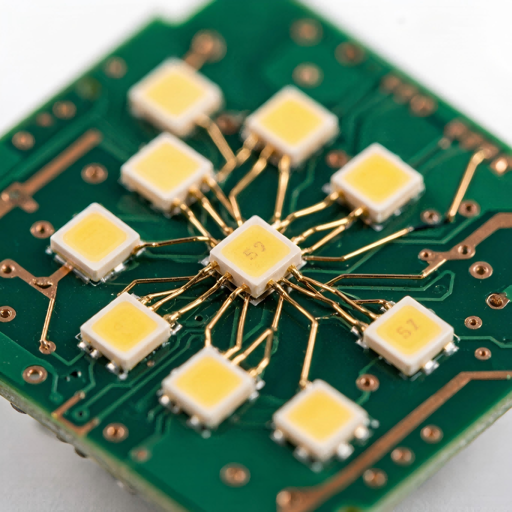
Figure 1: COB LED module macro close-up — chips directly bonded on PCB with silicone protective layer
Core Advantages of COB LED
- Higher Protection Rating: Silicone surface encapsulation provides IP65+ protection, far exceeding SMD in moisture, dust, and ESD resistance
- Wider Viewing Angle: No lens constraints, achieving 160°+ horizontal/vertical viewing angles
- Higher Contrast Ratio: Surface light source with deeper ink color, contrast ratio up to 10000:1
- Better for Fine Pixel Pitch: P0.4-P1.5 is COB's primary battleground where SMD yield drops sharply below P1.0
- Longer Lifespan: Lower thermal resistance, better heat dissipation, slower lumen decay
Why Does COB LED Need Professional Calibration?
COB packaging manufacturing processes inherently create potential brightness variations between pixels. Die placement precision, wire bond quality, and phosphor coating thickness all contribute to brightness inconsistency within the same batch of modules. Without professional calibration, the entire screen may exhibit uneven brightness and visible color differences, severely compromising display quality.
NovaLCT is designed to solve this core problem — through a systematic calibration workflow, it can elevate COB LED display brightness uniformity to above 97% and minimize color differences to imperceptible levels.
2. NovaLCT Software Features & System Architecture
NovaLCT is NovaStar's professional LED display configuration and calibration software, supporting a complete workflow from basic parameter configuration to advanced point-by-point correction. For COB LED display debugging, NovaLCT provides the following core functional modules:
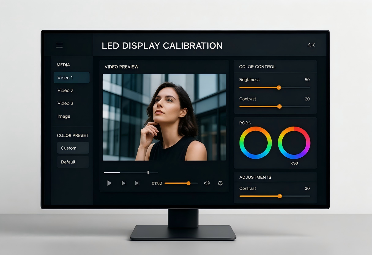
Figure 2: NovaLCT calibration software interface — featuring brightness adjustment, color correction, and preview functionality
| Module | Core Function | COB LED Applicability |
|---|---|---|
| Receiving Card Config | Scan mode, data flow direction, module size, routing setup | Required; COB modules need confirmed routing parameters |
| Brightness Calibration | Full-screen or zone brightness adjustment to eliminate inter-module differences | Critical for COB module brightness uniformity |
| Color Calibration | RGB color coordinate correction to eliminate color shift | COB white balance consistency requires focused correction |
| Point-by-Point Correction | Camera/luminance meter-based pixel-level brightness and color compensation | Highly effective for COB; strongly recommended |
| Gamma Correction | Set gamma curve for optimized grayscale transitions | COB surface light source requires tailored settings |
| Display Monitoring | Real-time monitoring of receiving card status, temperature, voltage | COB module temperature monitoring extends lifespan |
NovaLCT is the locally installed version, suitable for on-site debugging and offline operations. NovaLCT Connect is the cloud management version, supporting remote batch calibration and device management. For export promotion, we recommend introducing both tools to customers to reduce their technical support costs.
3. Hardware Preparation & Connection Setup
Before starting NovaLCT calibration, the following hardware preparation and system connections must be completed. Proper hardware connection is the foundation of successful calibration.
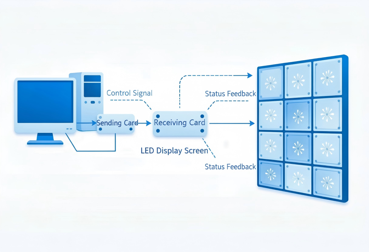
Figure 3: LED display calibration system connection topology — Computer → Sending Card → Receiving Card → COB LED Display
3.1 Hardware Checklist
- Computer: Windows 10/11, available USB port, latest NovaLCT installed
- Sending Card: NovaStar MSD300/MSD600 series, connected to computer via USB
- Receiving Cards: NovaStar MRV series (e.g., MRV416, MRV532-2), installed in each LED cabinet
- COB LED Display: Properly assembled COB LED cabinet module array
- Signal Cables: CAT6 ethernet (sending card to receiving card), ribbon cables (receiving card to modules)
- Calibration Equipment (for point-by-point): CCD luminance meter or professional calibration camera (e.g., NovaStar CLT-P1)
- Power Supply: Stable switching power supply, UPS recommended
3.2 Connection Steps
Download the latest NovaLCT from the NovaStar official website and install it on the debugging computer. After installation, open the software and confirm the sending card driver is properly installed (recognizable as MSD device in Device Manager).
Use a USB cable to connect the MSD300/MSD600 sending card to the computer. NovaLCT will automatically detect the connected sending card; the status bar showing "Connected" indicates success. If multiple sending cards are present, switch between them in the software.
Use CAT6 ethernet cable from the sending card's network port to the first cabinet's receiving card, then cascade from that receiving card to the next. The cascade order and data flow direction must match the physical cabinet arrangement. Each receiving card connects to its corresponding COB LED module area via ribbon cables.
The final step is power-on verification. First power on the control cards (sending card), then the display. Verify the display shows test patterns correctly (red, green, blue, white solid screens). If black screen, garbled display, or partial non-illumination occurs, troubleshoot hardware connections first.
Always power on control cards (sending card) first, then the display. For shutdown, reverse the order — display first, then control cards. Incorrect power-on sequence may cause receiving card configuration loss or chip damage, especially since COB modules are more sensitive to power stability.
4. NovaLCT Receiving Card Configuration
Receiving card configuration is the first and most fundamental step in NovaLCT calibration. Incorrect configuration will result in garbled display, artifacts, or missing colors.
4.1 Auto-Search Receiving Cards
After opening NovaLCT, navigate to the "Receiving Card" page and click "Read." The software will automatically search for all receiving cards on the cascade chain. After the search completes, the device list will display each receiving card's IP address, model, and firmware version. Verify the receiving card count matches the actual connections.
// NovaLCT Receiving Card Read Result Example
Card #1: 192.168.1.201 | MRV532-2 | Firmware v5.4.2
Card #2: 192.168.1.202 | MRV532-2 | Firmware v5.4.2
Card #3: 192.168.1.203 | MRV532-2 | Firmware v5.4.2
Card #4: 192.168.1.204 | MRV532-2 | Firmware v5.4.2
Total: 4 receiving cards connected
4.2 Configure Scan Mode
Scan mode determines the driving method of the LED module and is the core parameter of receiving card configuration. Common scan modes for COB LED modules are as follows:
| COB Module Pitch | Common Resolution | Recommended Scan Mode | Notes |
|---|---|---|---|
| P0.4 - P0.7 | 320×160mm / 80×40px | 1/16 ~ 1/32 Scan | Ultra-fine pitch, high scan ratio |
| P0.8 - P1.0 | 320×160mm / 40×20px | 1/16 ~ 1/32 Scan | Mainstream fine-pitch COB |
| P1.2 - P1.5 | 320×160mm / 27×13px | 1/16 ~ 1/20 Scan | Common for commercial displays |
| P1.5+ (rare for COB) | 320×160mm / varies | 1/8 ~ 1/16 Scan | Large pitch COB is uncommon |
How to configure: In NovaLCT, select the target receiving card, navigate to "Module Settings," and choose the corresponding parameter from the "Scan Mode" dropdown. If uncertain, consult the module supplier for the exact scan mode parameter.
Incorrect scan mode configuration is the most common cause of garbled COB LED displays. When purchasing COB LED modules, always request the complete module parameter sheet from the supplier, including scan mode, routing direction, module resolution, and data interface pinout. Quality suppliers should provide detailed technical specification documents.
4.3 Data Flow Direction & Routing
The routing method of COB LED modules determines the data signal transmission path. NovaLCT supports visual routing configuration:
- In the receiving card page, select "Routing Settings"
- Based on physical module arrangement, select routing type (left-to-right, right-to-left, top-to-bottom, bottom-to-top, Z-pattern, etc.)
- Set the number of modules per row/column
- Click "Apply" and observe whether the display shows test patterns correctly
- If the display is garbled, fine-tune the routing direction and reapply
5. COB LED Brightness & Color Calibration
Brightness and color calibration are the core stages of NovaLCT calibration, directly determining the final display quality of the COB LED display.
5.1 Brightness Calibration
The purpose of brightness calibration is to eliminate brightness differences between cabinets and modules, achieving screen-wide brightness consistency. NovaLCT offers two brightness calibration modes:
Mode 1: Manual Brightness Calibration
Suitable for quick on-site debugging. Steps:
- Switch the display to pure white screen
- In NovaLCT, select "Brightness Adjustment" function
- Select each receiving card and adjust its brightness percentage (0-100%)
- Use a luminance meter to measure the center brightness of each cabinet, using the lowest-brightness cabinet as baseline
- Reduce other cabinets' brightness to match the baseline
- Save settings and write to receiving cards
Mode 2: Automatic Brightness Calibration
When paired with a CCD camera or luminance meter, automatic calibration is possible. NovaLCT automatically collects brightness data from each zone, calculates compensation coefficients, and writes them to the receiving cards. This mode is more efficient and suitable for large-area COB LED displays.
COB LEDs are surface light sources without SMD reflector cups, resulting in different brightness attenuation curves. Key considerations: 1) COB brightness uniformity is typically better than SMD at factory level, but still requires calibration to reach 97%+; 2) COB module brightness decay is faster during initial burn-in (first 500 hours) and stabilizes afterward. We recommend performing the first calibration after 500 hours of module burn-in.
5.2 Color (Chromaticity) Calibration
Color calibration ensures screen-wide color consistency, eliminating RGB color shift. Key points for COB LED module color calibration:
- White Balance Calibration: Adjust RGB brightness ratio so the white field presents standard D65 white light (6500K color temperature). NovaLCT provides a white balance adjustment panel for fine-tuning RGB gain
- Color Coordinate Consistency: Use a colorimeter to measure color coordinates (x, y values) across zones. Inter-module color coordinate differences should be controlled within Δx≤0.003, Δy≤0.003
- Color Temperature Adjustment: Adjustable from 3200K (warm white) to 9300K (cool white) based on application. Command centers typically use 6500K; stage rentals commonly use 5600K
// NovaLCT Color Calibration Parameters Example
White Balance Settings:
  Red Gain:   100% (baseline)
  Green Gain:  98%  (fine-tuned)
  Blue Gain:   95%  (fine-tuned)
  Target Color Temp: 6500K
  Measured Chromaticity: x=0.313, y=0.329 (D65 standard)

Color Uniformity Targets:
  Target Brightness Uniformity: ≥97%
  Target Color Difference: Δx≤0.003, Δy≤0.003
6. Point-by-Point Calibration
Point-by-point calibration is NovaLCT's highest-level correction function, enabling independent brightness and color compensation for each LED pixel. For COB LED displays, the results of point-by-point calibration are particularly significant.
6.1 Why Does COB LED Need Point-by-Point Calibration More?
COB packaging bonds multiple LED chips directly to the PCB. Die placement precision, wire bond consistency, and phosphor coating uniformity all affect each pixel's light emission characteristics. Compared to SMD bulbs that have factory-level consistency, COB's inter-pixel differences depend more on manufacturing process control. Point-by-point calibration compensates for these manufacturing variations, achieving ultimate screen uniformity.
6.2 Point-by-Point Calibration Workflow
Install the CCD calibration camera or NovaStar CLT-P1 luminance meter, aimed at the display, ensuring the camera's field of view covers the entire calibration area. The recommended distance between camera and display is 3-5 times the display diagonal.
In NovaLCT, select the "Point-by-Point Calibration" module and choose the calibration mode (brightness / color / brightness+color). We recommend performing brightness point-by-point first, then color point-by-point.
NovaLCT will control the display to sequentially show pure red, pure green, pure blue, and pure white screens while the CCD camera synchronously captures brightness data for each pixel. During collection, ambient light must remain stable to avoid external light interference.
NovaLCT calculates brightness and color compensation coefficients for each pixel based on collected data. After calculation, the software displays a before/after comparison preview.
Click "Write" to store compensation coefficients in the receiving card's Flash memory. After writing, re-collect verification data to confirm brightness uniformity meets target. If not achieved, repeat the calibration process.
After complete point-by-point calibration, COB LED display brightness uniformity improves from factory-level 90-93% to 97-99%, with color difference ΔE controlled within 2, meeting professional-grade display standards. This is the core competitive advantage of COB LED modules in high-end applications such as command centers and broadcast studios.
7. Gamma Correction & Color Gamut Management
7.1 Gamma Correction Principles
Gamma correction affects the LED display's grayscale transitions and shadow detail performance. Higher gamma values provide richer shadow detail but darken the overall image; lower gamma brightens the image but loses shadow detail. Standard gamma values are 2.2 (sRGB standard) or 2.4 (broadcast standard).
In NovaLCT, gamma can be adjusted in the "Display Settings" page. For COB LED displays, we recommend:
- Command Centers / Surveillance: Gamma 2.2, balanced brightness and detail
- Broadcast / Virtual Production: Gamma 2.4, richer shadow detail
- Commercial Display / Advertising: Gamma 2.0-2.2, brighter to attract attention
- Stage Rental / Concerts: Gamma 1.8-2.0, high brightness priority
7.2 Color Gamut Management
COB LED modules typically achieve NTSC 110%+ color gamut coverage, far exceeding sRGB standard. NovaLCT supports color gamut mapping settings to ensure accurate color reproduction. Key parameters:
- Color Gamut Mode: sRGB (standard), DCI-P3 (cinema), Rec.2020 (ultra HD)
- Color Depth: 8bit / 10bit / 12bit; high-end COB modules recommend 10bit+
- Refresh Rate: ≥1920Hz (no scan lines when filmed); high-end COB can reach 3840Hz+
8. COB LED-Specific Calibration Considerations
Compared to traditional SMD LED displays, COB LED has unique technical considerations during calibration:
8.1 Light Distribution Characteristics
COB LEDs are surface light sources without SMD reflector cups and lenses, with a larger light dispersion angle. This means:
- Brightness attenuation is more uniform across viewing angles (viewing angle advantage)
- On-axis brightness may be lower than equivalent-pitch SMD; pay attention to brightness baseline setting during calibration
- The CCD camera's capture angle must be perpendicular to the display to avoid angular deviation affecting data accuracy
8.2 Silicone Surface Reflection
The silicone protective layer on COB modules can cause reflection under strong ambient light, affecting display contrast. During calibration:
- Turn off ambient light or use a light shield during point-by-point calibration
- Specular reflection from the luminance meter/camera should be filtered with a polarizing filter
- Calibration data already includes surface reflection compensation — do not use under non-standard ambient light
8.3 Long-Term Brightness Decay & Calibration Cycle
COB LED has better thermal performance than SMD, resulting in slower lumen decay, but periodic calibration is still needed to maintain optimal display quality. Recommended calibration cycles:
| Application | Daily Usage | Recommended Cycle | Calibration Content |
|---|---|---|---|
| Command Center / Surveillance | 24 hours | Every 6 months | Brightness + Color |
| Commercial Display | 12-16 hours | Every 12 months | Brightness primarily |
| Stage Rental | Intermittent | Every 3 months or after each setup | Brightness + Color + Point-by-Point |
| Broadcast Studio | 8-12 hours | Every 3 months | Point-by-Point |
9. FAQ & Troubleshooting Guide
Q1: Can NovaLCT be used for COB LED display calibration?
Yes. NovaLCT supports calibration for multiple LED packaging types including COB, SMD, and DIP. However, COB packaging has different light emission characteristics that require adjusted calibration parameters and methods. We recommend using NovaLCT v6.0 or later, which includes enhanced COB calibration support.
Q2: Why does a COB LED display need point-by-point calibration?
COB packaging bonds LED chips directly to the PCB. Manufacturing variations in die placement, wire bonding quality, and phosphor coating thickness can cause brightness differences between pixels. Point-by-point calibration compensates for these differences, achieving brightness uniformity above 97%, which is the key step for COB LED modules to meet professional display standards.
Q3: What hardware is needed for NovaLCT calibration?
Basic calibration requires: a computer with NovaLCT installed, a NovaStar sending card (e.g., MSD300), receiving cards (e.g., MRV series), and COB LED display cabinets. For point-by-point calibration, you also need a CCD camera or NovaStar luminance meter. When purchasing COB LED modules, confirm with the supplier whether complete technical support documentation is provided.
Q4: What is the difference between COB LED and SMD LED calibration?
The main differences are in light distribution and surface structure. COB LEDs have flat encapsulation without lenses, resulting in more uniform but wider-angle light distribution. SMD LEDs have reflector cups and lenses for more concentrated light. COB calibration requires attention to brightness attenuation compensation, color temperature consistency, and post-calibration long-term stability.
Q5: How to troubleshoot garbled display or partial non-illumination?
Follow this troubleshooting sequence: 1) Check receiving card power LED status; 2) Verify ribbon cable connections are secure and correctly oriented; 3) Re-read receiving cards in NovaLCT to confirm connection status; 4) Check scan mode is set correctly; 5) Verify routing direction matches physical module arrangement; 6) If unresolved, contact the module supplier's technical support.
Q6: What to do if color patches or color differences appear after calibration?
This may be due to incorrectly written calibration data or ambient light interference during data collection. Solutions: 1) Re-write calibration data and verify; 2) Turn off ambient light and re-collect; 3) Check CCD camera alignment; 4) Confirm modules have passed burn-in (500+ hours recommended). If issues persist, use NovaLCT's "Zone Calibration" function to manually adjust abnormal areas.
10. Conclusion & COB LED Module Selection Guide
NovaLCT, as the core tool for COB LED display calibration, can elevate COB LED module display quality to professional-grade standards through a systematic workflow of receiving card configuration, brightness/color calibration, and point-by-point correction. For export promotion and procurement decision-makers, understanding calibration technology not only aids product selection but also enables providing professional technical service support to customers.
Technical Recommendations When Selecting COB LED Modules
- Verify Parameter Completeness: Quality suppliers should provide complete module specification sheets including scan mode, routing direction, resolution, brightness, and color coordinates
- Aging Test Report: Modules should undergo 48+ hours of aging testing before shipment to ensure stability
- Brightness Uniformity: Factory brightness uniformity should be ≥93%, and ≥97% after calibration
- Protection Rating: COB modules should achieve IP65+ with moisture and dust resistance
- Technical Support: Suppliers should provide NovaLCT configuration files and technical support services
- Warranty: We recommend selecting COB LED module suppliers offering 3+ year warranties
If you are looking for a high-quality COB LED module supplier, feel free to contact us for detailed product specifications, NovaLCT configuration files, and technical support solutions. We provide full pitch range COB LED modules (P0.4-P1.5) with complete calibration technical guidance.
Get Professional COB LED Module Solutions
We provide full pitch range COB LED modules (P0.4-P1.5) with NovaLCT calibration technical guidance and complete specification sheets. Whether you're a system integrator, rental provider, or end user, we have the right solution for you.
Contact Us for Quote & Technical Solution