1.1 Background
Command centers are essential facilities for various industries such as government, manufacturing enterprises, firefighting, and more. They serve critical functions including day-to-day operations, command decisions, emergency event management, visitor reception, and more. A modernized command center should be led by command and information technologies, making full use of advanced technologies such as electronics, networking, and communications. It should be designed as a hub for data and multimedia information, where information and data are shared, human-computer interaction supports decision-making, information is updated in real-time, and video conferences are held. Command centers display vast amounts of data, videos, video conferences, decision platforms, and more, assisting decision-makers in effectively filtering and interpreting information and facilitating the execution of decisions.
During emergencies, effective command requires low-latency, smooth, and high-quality signal displays. Analog videos, IP, digital video images, live-feed video images, ultra-high-definition software, map software, video conference images, and other content from independent systems all need to be integrated into a unified control system. Therefore, the overall design of image control places higher demands on the functionality and performance of the control system. Sharing of voice, video, images, data, and other information resources allows for comprehensive and unified command and dispatch, enabling command and dispatch to be carried out quickly and efficiently.
Improving display quality, unified platform dispatch, and multi-center coordination have become top priorities.
1.2 Objectives
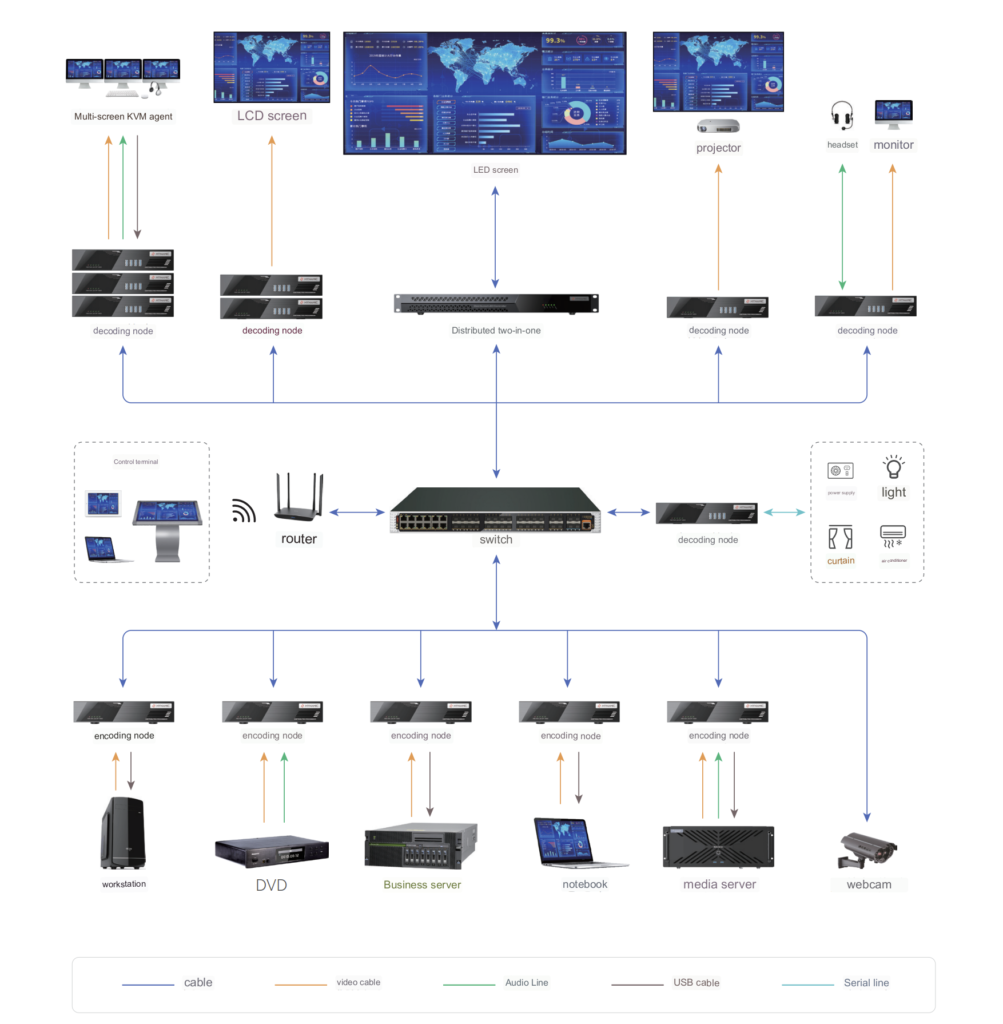
The distributed splicing controller consists of three main components: the server, input nodes, and display nodes. The server is responsible for managing the entire system, display nodes handle decoding and displaying, and input nodes manage signal source input and encoding, effectively allowing integration with any video source and displaying it on the screen.
As a video control device, the distributed splicing controller supports real-time video processing at 60fps, with a system display latency as low as 10ms, ensuring real-time information delivery and smooth visuals. It employs lossless visual processing, resulting in finer image details. Signal switching and scene operations are completed within milliseconds, ensuring rapid responsiveness.
All devices in the distributed splicing controller are connected via a network, enabling long-distance transmission. One system can control multiple video walls, unifying management and control across multiple command centers located at a distance. While ensuring practicality and security, it guarantees the system’s overall advancement and openness.
The goal is to establish a fully functional, reliable, easy-to-manage, and expandable distributed splicing control system. This system aims to integrate command and decision-making, enhance emergency response efficiency, and conserve scheduling resources.
1.3 Design Principles
Due to the need for security and efficient management, the design of the distributed splicing controller system adheres to the following principles:
Practicality In accordance with user requirements, the primary principle is practicality. The system must fully meet the actual needs of the display control system. It should employ current mainstream computer application technologies and relatively mature management models, while considering future development requirements. It’s essential to avoid blindly pursuing advanced system design and extravagant equipment. Comprehensive planning and a pragmatic approach are key.
Security The construction of the system requires the integration of past construction experience and specific application requirements of display control. A system architecture with mature application practices ensures robustness. High reliability and security are achieved by selecting equipment with tens of thousands of hours of average fault-free operation and designing redundancy backups for critical equipment and components. Robust mechanisms for secure and stable system operation and the development of operational fault contingency plans are established to ensure smooth system operation from all angles.
Advancement The system design follows the principles of systems engineering. Through scientific and rational design, it prevents the pursuit of a single high specification while fully embodying the system’s advancement. Advanced, mature, and reliable equipment is chosen, and advanced security technologies with broad development prospects are maximally utilized. The goal is to create an upgradable, scalable, and compatible system and application platform, building a digital, intelligent, and efficient display control system.
Openness The system design adheres to standardized design and strictly follows international, domestic, and industry standards for relevant technologies. This ensures transparency and interactivity between systems and considers connections with other business systems. Future expansion requirements are scientifically predicted, and ample design margin is incorporated into the design and equipment selection.
Ease of Management and Maintenance The system should be easy to manage and maintain. Specialized tools such as network management and self-diagnostic programs facilitate the monitoring of the operational status of devices and networks. The design of information infrastructure, such as computer networks, should adopt a simple and user-friendly architecture to reduce system operation and maintenance costs.
1.4 Design Basis
The design of the distributed splicing controller system is based on the following standards and specifications:
- GB 50174-2008: Design Specification for Electronic Information System Computer Rooms (Achieving Class A Standards)
- GB 50462-2008: Construction and Acceptance Specification for Electronic Information System Computer Rooms
- GB/T 2887-2000: General Specification for Electronic Computer Site
- GB 50343-2004: Technical Specification for Lightning Protection of Building Electronic Information Systems
- YD/T185-1999: Specification for Distribution Equipment Used in Telecommunication
- GB50052-2009: Design Specification for Power Supply and Distribution Systems
- GB 50303-2002: Construction Quality Acceptance Specification for Electrical Engineering of Buildings
- GB4943.1-2011: Safety Requirements for Information Technology Equipment
- GB 50057-2010: Design Specification for Lightning Protection of Buildings
- GBJ79-85: Design Specification for Communication Grounding
- GBJ19-87: Design Specification for Heating, Ventilation, and Air Conditioning
- GBJ54-83: Design Specification for Low-Voltage Distribution Devices and Lines
- GA/T75-94: Engineering Procedures and Requirements for Security and Protection
- GB50395-2007: Design Specification for Video Security Surveillance Systems
- GB50314-2006: Standard for Intelligent Buildings Design
- GB/T50339-2003: Quality Acceptance Specification for Intelligent Buildings
- GB6650-86: Technical Conditions for Access Floors in Computer Rooms
- JGJ/16-2008: Design Specification for Electrical in Civil Buildings
- GBJ32-92: Construction and Acceptance Specification for Electrical Installation Projects
- JGJ73-91: Construction, Installation, and Acceptance Specification for Building Decoration Projects
- SJ/T10796-2001: General Specification for Anti-static Access Floors
- GB50054-2011: Design Specification for Low Voltage Distribution
- GB50222-2001: Fire Prevention Design Specification for Interior Decoration of Buildings
- YD/T754-95: Telecommunication Equipment Room Electrostatic Protection Regulations
- GB50348-2004: Technical Specification for Safety and Protection Engineering
- GB9175-88: Environmental Electromagnetic Hygiene Standards
- GB8702-88: Electromagnetic Radiation Protection Regulations
- IEC801: Electromagnetic Compatibility Standards
- GB/T12190-2006: Measurement Method for Shielding Effectiveness of High-Performance Shielded Rooms
- ISO/IEC 24764: Information Technology – Generic Cabling for Data Center Premises
- ISO 11801: International Generic Cabling Standard for Building Cabling
- GB 50311-2007: Design Specification for Integrated Cabling Systems
- CECS72:97: Construction and Acceptance Specification for Comprehensive Cabling Systems in Buildings and Building Complexes
- ANSI/TIA/EIA-942A: Telecommunications Infrastructure Standard for Data Centers
These standards and specifications provide the foundation for the design, ensuring compliance with industry best practices and safety regulations.
Chapter 2: System Solution
2.1 System Overview
As the times have evolved, various command centers have moved away from a single-center command model. The construction and application of command centers have made significant progress, gradually transitioning from traditional experiential models to modern high-tech strategies.
The distributed splicing controller, based on the foundation of a powerful encoding and decoding splicing control, is a large-screen control device designed for the distributed splicing market. The entire system employs a decentralized design and consists mainly of input nodes, output nodes, cluster gateways, and more. Output display nodes are responsible for decoding and displaying, while input nodes handle signal source access and encoding. The system architecture is simple, convenient, and easy to maintain. It utilizes various visual management tools for operations, enabling video signal preview and offering user-friendly flexibility. The interface is clean, the operation is straightforward, and intelligent processing eliminates unnecessary steps.
The system can integrate multiple systems, including video, audio, central control, etc., and also enables remote control and management. It simplifies system architecture, making deployment and maintenance more accessible. Through distributed system architecture and high-performance video transmission algorithms, it addresses challenges related to audio and video interconnection, communication, and control. It resolves issues often encountered in centralized systems, such as poor equipment fault tolerance, expansion difficulties, and space constraints.
Notably, the KVM seat management control allows for unified management and scheduling of computer hosts and peripherals. It also offers strict permission division at the seat end, ensuring hierarchical functionality usage within the seat management system. The system facilitates personnel interaction, seat management, centralized control, and allows for customized permission settings, all independently operated.
The seat collaboration system enables features such as one person managing multiple machines, multiple people using one machine, human-machine separation, and seat collaboration. Each user can simultaneously view online operating accounts. The flexible interaction feature enables interaction content to be sent from the sender to the receiver, allowing the receiver to freely allocate content to various displays, breaking away from passive screen reception. Under the KVM over IP architecture, it achieves signal takeover and seamless signal push. The pure distributed architecture supports unlimited expansion, meeting future expansion needs.
The system is widely applied in large command centers and multiple center and multiple command room scenarios, connecting audio, video signals, and control signals among various sub-control centers. It achieves the goal of signal sharing and unified control among each sub-center. The system solution meets the current needs of users while considering future expansion requirements during the design phase. The system not only demonstrates outstanding performance but also offers exceptional cost-effectiveness. Each node can operate independently, and a failure in any one node will not affect other nodes, thereby enhancing the overall system’s stability. It allows for quick replacement of faulty nodes to restore the system. The goal is to realize large-scale command centers, manage multi-channel video inputs and outputs, and manage multiple data sources to achieve data interoperability, maximizing the practical value the system brings to users.
Typical Application Patterns of Distributed Systems
The typical application patterns are as follows:
Different signal sources, such as 4K signal sources, laptops, DVDs, video conferencing terminals, etc., are unified and converted into a network through input nodes. They are then transmitted over the network to output nodes for decoding and display on large screens in control centers, command centers, video conferencing rooms, and more. If the front end directly connects to network cameras, it can decode and display on large screens directly through the network to output nodes. The entire distributed system combines powerful system functions such as visual management, KVM seat collaboration, image switching, large-screen splicing, long-distance transmission, audio-video matrix, centralized control management, projection fusion, and more.
In the same functional scenarios or scenarios requiring remote centralized management, distributed splicing controllers can reduce equipment configuration, simplify equipment wiring, shorten construction periods, achieve lossless cross-use of signals, and provide users with high-quality experiences.
2.2 System Features
Security: The system follows a decentralized structure and does not rely on servers. It lacks centralized plug-in devices, ensuring that the failure of any single node does not affect the functionality of other channels. All other links can continue to work normally.
Scalability: The decentralized structure of the system allows for easy scalability. You can easily increase the number of nodes based on changes in project scale without theoretical limits. The expansion process is simple and convenient, without the need to interrupt the system. There are no risks associated with operations like cutting or connecting. You only need to add new nodes to the system.
Ease of Maintenance: Nodes can be installed in various ways, either in server racks or close to signal sources and display devices. The system offers flexible wiring options, and the management software can perform routine maintenance on any node without affecting the overall operation.
2.3 Application Scenarios
2.3.1 Large-Scale Command Center Scenarios
2.3.1.1 Scenario Description Large-scale command and control centers require functionalities beyond those of regular or small-scale command centers. They often face more complex situations, such as a wide variety of signal sources, inconsistent input signal formats, different transmission methods, varying input stream sizes, and complex display requirements.
In scenarios like conventional command and control, dispatch, and operations centers, multiple features are typically needed. These include multi-screen splitting and display, periodic background switching, multi-scene switching and pre-planning, support for arbitrary window opening, and the ability to collect image data from different signal sources, handle emergency events, and provide flexible scalability. These centers require capabilities in communication, information processing, audiovisual technology, and more.

2.3.1.2 Function Introduction
In the construction of large-scale command and control center scenarios, traditional centralized controllers have limitations due to the constraints of their chassis. They have a maximum limit on the number of signal sources that can be connected. When there are many signal sources, some may not be displayed on the screen. The distributed splicing controller can support the management and connection of up to 1600 signal sources. It can support arbitrary expansion of input and output nodes, meeting the later requirements for additional signal sources and larger screens. It uses the H.264/5 standard, which has a small network bandwidth occupancy rate, reducing the demand on the user’s network and lowering costs.
Supported by synchronization technology, the entire system, in addition to having all the functions of traditional splicing controllers such as spanning screens, roaming, and overlay, can achieve sub-second scene switching response and sub-second window opening. It also has unique advantages such as large-scale splicing display synchronization.
2.3.1.2.1 Ease of Expansion
Compared to traditional centralized controllers, which have limitations due to their chassis, the number of signal sources that can be connected is limited and cannot be very large, usually around one or two hundred. This limits the ability to simultaneously connect and display a large number of signal sources.
The distributed structure, on the other hand, is designed to accommodate future expansion needs. To expand the system, you only need to add the corresponding number of nodes to the system. There are no limitations on input nodes, allowing for unlimited expansion. Thanks to its excellent scalability, when the system expands, administrators in the command center only need to add the new devices to the location group, completing the entire system upgrade and expansion process.
2.3.1.2.2 Ease of Management
In traditional large-scale applications with multiple video inputs and outputs, the limited support for input and output points, multiple decoders, multiple matrices, and numerous peripheral devices can lead to complex operations and inconvenient management. When a node experiences an issue, it needs to be located and resolved. With a large number of devices deployed on the same site and a multitude of cables, locating the problematic node can be difficult, reducing efficiency in problem resolution and impacting user device usage.
The use of a distributed system offers several management conveniences:
- Supports multi-screen management, with a single screen supporting multiple scenarios and multiple presets.
- Node devices can be added online, facilitating system upgrades and expansion.
- Unified interface management, where all audio and video interfaces are converted into common network interfaces through encoding nodes.
This approach simplifies the management of the entire system, making it more efficient and user-friendly.
2.3.1.2.3 Structural Stability
- Distributed Architecture: The use of a distributed architecture means that each node can operate independently. If one node experiences a failure, it will not affect the operation of other nodes, thereby enhancing the overall system’s stability. Additionally, faulty nodes can be quickly replaced to restore the system.
- Scalability: The distributed structure is designed to accommodate future expansion needs. To expand the system, you only need to add the corresponding number of nodes to the system. There are no limitations on input nodes, allowing for unlimited expansion.
2.3.1.2.4 Low Network Requirements
The entire system utilizes the H.264/5 standard, resulting in a minimal network bandwidth utilization rate. This reduces the demands on the user’s network and lowers costs. The system also employs low-bitrate encoding technology, saving bandwidth by 50%, thus achieving a truly low-bandwidth high-definition experience.
2.3.1.2.5 Excellent Display Quality
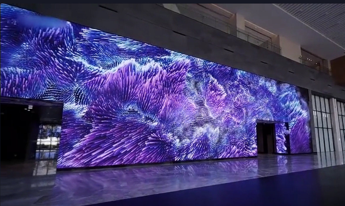
- The system offers a 60Hz output for the video wall, ensuring that motion images do not flicker or tear, even during extended viewing sessions without causing visual fatigue.
- It supports the input of 4K ultra-high-definition signals, with a resolution of up to 4096×2160, which is four times that of 1080p full HD, resulting in clear and detailed image edges.
2.3.2 Multiple Centers, Multiple Control Room Scenarios
2.3.2.1 Scenario Description
In real-world applications involving multiple centers and control rooms, there are scenarios where different departments, including the Information Center, Intelligence Center, Data Center, etc., are all under a comprehensive management department. This is equivalent to having several large screens at different locations, such as meeting rooms on different floors or even command centers in different locations. The meeting rooms are physically distant from each other. Typically, each location’s large screen is independently connected and controlled by its own matrix and decoder, making it difficult to achieve interconnectivity.
The challenge is how to achieve data sharing and efficient display without delay between different meeting rooms physically separated on different floors or locations, achieving information fusion.
Through network transmission, it is possible to achieve long-distance transmission with minimal front-end equipment and simple connections. Only one set of software is required on the back end. The required devices are extremely simple, and control is entirely implemented by the back-end software, eliminating the need for a large number of traditional analog monitoring system devices, such as expensive matrices, screen splitters, switchers, and host devices for video-to-network conversion. Image transmission through comprehensive cabling networks eliminates the need for extensive coaxial cables, reducing costs. It also provides strong scalability and extension capabilities without the need to modify existing cabling.
2.3.2.2 Functional Overview
The distributed splicing controller can integrate multiple systems, including video, audio, and central control operations, allowing for remote control and management. Through a distributed system architecture and high-performance video transmission algorithms, it resolves the challenges of audio and video interconnection, communication, and control. It connects the audio, video, and control signals between various control centers, achieving the goal of signal sharing and unified control among all control centers.
In scenarios with multiple centers that require coordinated control and display, the distance between Center A and Center B can be quite extensive, reaching several kilometers or more. Traditional video cables are incapable of transmitting signals over such long distances, preventing video exchange and coordination between centers.
The distributed splicing controller relies on network transmission for all input and output signals. It also supports non-IP signal transmission through receiver boxes, enabling long-distance transmission. A single receiver box can accommodate 2 HDMI inputs, 2 DVI inputs, 2 VGA inputs, and 1 4K signal input, encoding and outputting them. The encoding technologies used are H.265 and H.264. This entire process is characterized by simple cabling and excellent scalability. When expanding the system, management personnel only need to add the new equipment to the location group, completing the entire system upgrade and expansion process. Additionally, this network can be used for data transmission and collaborative data sharing among departments, achieving long-distance communication.
2.3.2.2.1 Multi-Center Fusion and Shared Management
This feature allows data sharing under physical isolation conditions, enabling efficient and delay-free display and achieving information fusion. Multiple centers can share signal sources.
In scenarios where multiple centers need coordinated control and display, such as displaying Center A’s content on Center B’s screens, even when Center A and Center B are physically distant, with distances reaching several kilometers or more, traditional video cables cannot transmit signals over such long distances, preventing video exchange and coordination between centers. The distributed splicing control system, on the other hand, can effectively address this issue by connecting through the network, enabling long-distance communication.
2.3.2.2.2 Long Transmission Distances
All input and output signals of the distributed splicing controller are transmitted through the network. By using encoding nodes, all audio and video interfaces are converted into universal network interfaces. Typically, the maximum distance for video transmission using video cables is around 15 meters, and beyond this distance, the signal may degrade. However, the system can accommodate non-IP signals for long-distance transmission. When connected to a cluster gateway, the transmission distance can reach up to 200 meters. This entire process involves simple cabling and easy maintenance.
Long transmission distances facilitate stocking, construction, and fault handling. Input nodes are deployed using standard Ethernet cables, allowing for long-distance transmission, making it convenient for project implementation and deployment.
2.3.2.2.3 Visual Control on the Platform
The system allows real-time viewing of signal source content and television wall content through the client, ensuring that users can view the television wall display content in real-time while performing television wall operations, ensuring correct and efficient operations.
The system’s signal sources and all screens can be controlled and managed through PAD terminals. Any signal source content can be switched to the television wall or switched through one-click preset scene scenarios, ensuring correct and efficient operations.
2.3.2.2.4 Rapid Scene Switching
Signal switching and scene operations are completed within a hundred milliseconds, providing rapid response. The switching process is free from black screen flashes or flickering and is achieved through a unique synchronization optimization technology. The synchronization time difference control between the output nodes of the television wall is within 10 microseconds. This ensures that the displayed images are completely synchronized, even for fast-moving objects, with no tearing.
2.4 System Functions
The distributed controller is designed for the distributed splicing market, addressing issues encountered in centralized projects such as poor device fault tolerance, difficulty in expansion, and site limitations. It offers extensive device management functions, allowing device activation, network configuration, and television wall management through the client. It possesses powerful video image processing capabilities, enabling functions like image splicing, scaling, moving, roaming, and screen splitting.
2.4.1 Splicing and Display Functions
2.4.1.1 Splicing Display
Real-time video signals can be displayed on the screen, achieving functions such as image splicing and full-screen display.
2.4.1.2 Window Opening and Roaming
Each output window can scale or move the signal source window to meet user requirements for multi-screen splicing, arbitrary window opening, and roaming. Users can freely drag the position of floating windows, zoom windows, roam windows, and split windows. The system also supports adjusting the transparency of windows and splicing and displaying window images.
2.4.1.3 Stretching and Scaling
Users can stretch and scale the displayed images as needed, and the images after stretching and scaling will not become distorted or damaged.
2.4.1.4 Split Display
The distributed controller supports multi-screen split display on a single screen, allowing multiple signal sources to be connected.
2.4.1.5 Multi-screen Display
The distributed controller not only supports displaying a single image on each screen but also has built-in matrix functionality, allowing a single signal source to open multiple windows and display them simultaneously.
2.4.1.6 Arbitrary Combination Display
The distributed controller can combine any images for display without a fixed combination mode, enabling various display effects to meet various user display needs.
2.4.1.7 Network Screen Capture
The distributed controller can project the operating interface of a remote computer onto the display wall through a remote network connection. For example, this can be applied to client demonstrations and other scenarios.
The primary function of the splicing controller is splicing and displaying images. When splicing and displaying images, the synchronous effect of the images greatly affects the viewing experience. Conventional splicing controller devices can achieve frame synchronization, but the latest advanced splicing controllers can achieve pixel-level synchronization, effectively solving the image synchronization problem. There is zero delay between spliced images, providing users with a high-quality viewing experience.
2.4.2 Distributed Seat Collaboration Management Features
2.4.2.1 Cross-Screen Operation, Rapid Data Retrieval
Seat operators can take control of corresponding host signals by simply moving the mouse cursor to the respective computer screen. When switching keyboard and mouse control to the corresponding host, simply move the mouse cursor to the desired computer screen, maintaining a clean user interface. The system supports single-row screens, double rows, or multi-row planar roaming switching. The system supports OSD quick screen display control, where operators can tap hotkeys to take control of the required computer host on-demand, achieving full keyboard control. This greatly improves operator response speed, enabling rapid data retrieval and timely response, maximizing work efficiency.
2.4.2.2 Single-Screen Window Management
A single screen can be divided into multiple windows, with various preset modes available. Users can freely set the cascade relationship of multiple windows. Direct “what you see is what you get” keyboard and mouse operations can be performed on target computers (including computers with different operating systems).
2.4.2.3 Timely Data Sharing
Seat administrators can use the current keyboard and mouse to invoke the OSD quick control menu using hotkeys. With a simple keystroke, screen display signals can be pushed to any display or output node in the system, achieving efficient data sharing for effective command.
2.4.2.4 Secure Data Isolation
Operators do not need to install any PC software and interact with seat content through network interfaces, ensuring that business systems and control systems cannot be physically connected. The system’s business network and control network are physically isolated, and the business network cannot access the control network in any way, ensuring information security and data isolation for secure command operations.
2.4.2.5 Hierarchical User Management
Based on operator accounts, permissions, content push, and audio-video interactions can be achieved. Different management permissions can be set for corresponding administrators using a hierarchical user management model, such as leader seats, team leader seats, and ordinary seats, each with different access and management permissions.
2.4.2.6 Instant Data Interaction
Operators do not need to go through the cumbersome process of traditional KVM matrix operation. They can directly invoke the OSD quick menu using hotkeys. By entering a number and hotkey combination, they can immediately take control of the required host (get function). When collaboration is needed, the current operating host can also be directly pushed to other seats or output nodes for task handover and information sharing (push function).
2.4.2.7 Strict Permission Control
Administrator seats can group various sub-seats. Depending on actual needs, different seats can have different control rights over hosts and display screens. This ensures that each seat operator only has control rights over hosts and display screens related to their job attributes (permissions can be comprehensive control, view-only, no access, or a combination of various permissions). This ensures strict permission allocation, data confidentiality, and enhanced collaborative capabilities, increasing work efficiency and precision.
2.4.2.8 Data Security and Confidentiality
Within the control network, each seat unit can only be accessed with an account and password. Critical information such as passwords is encrypted and decrypted using DES, ensuring that network personnel, even if they intercept data, cannot access user information or perform unauthorized access or control. In actual projects, temporary permissions may be required to allow another operator to take over work when an operator temporarily leaves their seat (temporary permissions must expire immediately upon the operator’s return).
2.5 Product Advantages
2.5.1 Distributed Architecture
- Utilizes a distributed architecture where each node can operate independently.
- Failures in one node do not affect other nodes, enhancing system stability.
- Quick replacement of faulty nodes facilitates system recovery.
- Scalable for future expansion with no limits on input nodes, allowing for unlimited expansion.
- Flexible deployment of input and output nodes based on the physical topology of signal sources and screens, reducing rack usage and construction costs.
2.5.2 Visual Control
- Traditional large screen control and management often rely on control software combined with keyboards and PC-based client software for functions like video point preview, rotation, scene switching, etc.
- However, these methods can’t provide perfect previews of signal quality or display content, which is crucial.
- The distributed splicing controller series introduces a visual signal management solution that supports multi-signal source simultaneous preview, video wall playback, and remote desktop interaction through various clients (WEB client, iPad client, and Android Pad client).
- This addresses the need for human-computer interaction in visualization systems and communication for decision-making.
- The distributed splicing controller features low input and output latency and complete synchronization between different outputs, effectively enhancing the effectiveness of visual operations.
- Multiple signal source previews: Simultaneously preview multiple signal sources in the signal source list, allowing real-time monitoring of all signal sources’ content.
- TV wall playback: Window layouts and content on the TV wall can be displayed in real-time on the TV wall client, improving the accuracy and intuitiveness of remote TV wall operation.
2.5.3 Open Protocol Standards
- The system supports H.265 video encoding and decoding algorithms.
- It supports international and national video access protocols such as ONVIF, RTSP, GB28181.
- Nodes directly support high-performance decoding without the need for additional decoding/transcoding devices, saving on system construction costs.
2.5.4 High-Performance Decoding
- In video surveillance applications, network video images are the primary video signals.
- Traditional methods involve using network decoders to convert network video signals into standard video signals (e.g., VGA, DVI, HDMI), which are then input into the image splicing controller, adding complexity and an additional conversion step.
- The distributed splicing controller combines high-performance video decoding capabilities with convenient large screen splicing control, making it easy to display various network video images on the screen.
- It also provides signal preview for easy user signal call-up.
- A single decoding and display node supports up to 16 channels of 1080P or 32 channels of 720P or 64 channels of D1 decoding and display.
- Output resolution can reach 1920*1200 and supports local video file playback on the screen.
- The distributed splicing controller does not perform frame-dropping or frame-averaging mechanisms on input video signals.
- Input signals with a frame rate of 60fps are directly processed and transmitted to the output at the original 60fps, ensuring smooth and high-quality display without stuttering or jitter, meeting the requirements of scenarios with high display quality.
2.5.5 Lossless and Low-Latency Video
- Achieves industry-leading zero-latency video display with system display latency as low as 10ms, ensuring real-time information transmission.
- Signal switching and scene operations are completed within a hundred milliseconds, ensuring rapid response.
2.5.6 Seamless Scene Switching
- Scene switching responds quickly, completing transitions within 1 second with no black screens or flickering.
- High-precision synchronization of splicing screens ensures completely tear-free splicing images.
2.5.7 Synchronized Display of Splicing Images
- Many standard splicing controllers on the market are limited by hardware capabilities and cannot process 60 frames per second (60 continuous images per second) within 1 second.
- They typically discard half of the video data before processing, reducing it to 30 frames per second, and simply copying the output after processing.
- This approach causes flickering in motion scenes, which is especially noticeable on high-brightness LED screens.
- Ordinary splicing controllers may have synchronization issues between output ports, leading to unsynchronized displays on connected LED screens, resulting in tearing, which is particularly pronounced on seamless LED screens.
- The distributed splicing controller solves this problem by using a unique synchronization optimization technology, ensuring that the output synchronization delay between each display node in the video wall is within 10 microseconds.
- This results in completely synchronized images for users, even in fast-moving scenes, with no tearing.
2.5.8 4K Ultra-High-Definition Support
- Supports the input of 4K ultra-high-definition signals with a resolution of up to 4096*2160, which is four times the resolution of 1080P full HD, offering sharp and detailed image edges.
2.5.9 Ultra-High-Resolution Display
- To achieve better visual effects, customers often have high-resolution requirements for videos and images.
- Using single-unit display units with HDMI interfaces and a resolution of 1080P for multi-screen display can ultimately achieve 4K resolution requirements.
- The distributed splicing controller addresses the need for high-definition content by splitting and displaying ultra-high-resolution videos and images in a distributed manner.
2.5.10 Long-Distance Signal Transmission
- In scenarios where multiple centers need coordinated control and display, such as displaying Center A’s content on Center B’s screens, the distance between Center A and Center B can be quite substantial, reaching several kilometers or more.
- Traditional video cables cannot transmit signals over such long distances, leading to the inability for centers to view each other’s video and achieve coordination.
- The distributed splicing controller, however, overcomes this problem by connecting through a network, enabling long-distance communication and coordination.