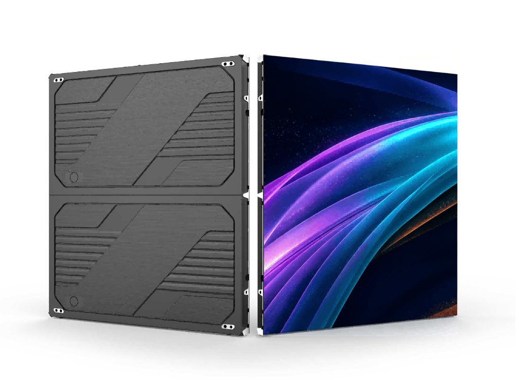
COB LED Display Calibration Explained: Brightness, Chromaticity & Gamma Fundamentals
A fine-pitch COB wall that passed acceptance with clean whites and deep blacks shows subtle patches a year later—brighter zones here, a reddish tint there, mosaicism creeping across dark scenes. The wall isn't defective. Its millions of LEDs are simply aging and drifting, each at its own pace. The discipline that keeps them marching in step is LED display calibration.
01What Calibration Actually Fixes
Start with a mental shift: an LED display wall isn't "one screen." It's a choir of hundreds of thousands—on large fine-pitch walls, tens of millions—of independent emitters. That's fundamentally different from LCD, where every pixel is patterned on the same glass substrate and behaves almost identically. On an LED wall, every pixel is three physically separate chips—red, green, blue—each with its own brightness, its own color, its own temperament.
No two voices in the choir match, and the symptoms are predictable:
- dirty, uneven whites on full-white content;
- mosaicism and blotches that explode in dark, low-gray scenes;
- progressive worsening as the display ages.
Calibration is essentially a per-pixel alignment routine, done in three steps:
Calibration cameras or luminance colorimeters capture the actual brightness and chromaticity of every pixel
Each pixel is compared against target values to generate per-pixel correction coefficients
Coefficients are written back to the receiving cards and applied in real time on the output side
The payoff spans engineering and business:
- Image-quality foundation: without uniformity, contrast and color accuracy are meaningless;
- Effective lifespan: recalibration restores an aged wall close to factory-grade uniformity—no replacement needed;
- Cost control: for packages where single-lamp repair is impossible (like COB), calibration is the main lever for lifecycle quality;
- Fast recovery: rental walls and cabinet swaps regain full-screen consistency quickly after calibration.
02Five Sources of Brightness & Color Variation
Why are LEDs inherently uneven? Chapter 1 of the textbook LED Display Calibration Technology organizes the root causes systematically. Here they are as "two by birth, three by service."
LED chips vary across the wafer due to process spread. Manufacturers sort lamps into bins by brightness and wavelength—but a bin is a range, not a point. Lamps within the same bin still differ visibly, and cross-bin mixing makes it worse. Since red (AlGaInP) and green/blue (InGaN) come from entirely different material systems, their wavelength distributions behave differently—white balance never comes for free.
Different production batches, packaging houses and production lines carry systematic offsets. Once a display factory mixes lamp lots, those offsets are frozen into the wall.
Constant-current driver ICs have channel-to-channel current tolerance; PCB trace impedance and voltage drops vary across the board. Current differences become brightness differences, one scan line at a time.
Light output and dominant wavelength both drift with junction temperature—and red LEDs are the most sensitive: output drops and wavelength shifts red as they heat up. Cabinet temperature is never uniform (power supplies and driver boards create hotspots), so many "color patches" on a wall are, in effect, temperature maps.
After thousands of hours, LED output decays—and red, green and blue decay at different rates (red typically fastest). White balance drifts globally while local non-uniformity intensifies. That's exactly what the one-year-old wall in our opening looked like.
03Three Concepts: Luminance, Chromaticity, Gamma
Three quantities anchor everything in calibration. One line each: luminance defines how bright, chromaticity defines what color, gamma defines how grayscale transitions.
Luminous intensity per unit area, measured in cd/m² (nits). Typical figures: indoor COB meeting and control-room displays run 600–800 nits, rental walls around 1,000 nits, outdoor walls above 5,000 nits.
Engineering view: the eye is relatively forgiving on brightness—small percentage differences are hard to detect when not directly adjacent. Brightness calibration decides white-field consistency.
A color's position on the CIE 1931 chromaticity diagram, described by (x, y) coordinates, independent of luminance. Related ideas: correlated color temperature (CCT), dominant wavelength, gamut coverage, white balance.
Engineering view: the eye is far more sensitive to color than brightness—tiny chromaticity offsets between adjacent areas are immediately visible. Chromaticity calibration is the main battlefield of uniformity, and it re-balances the RGB mixture at some cost in brightness.
The display's grayscale-to-luminance transfer relationship, approximated by a power function: output ∝ (input gray / max gray)^γ. It exists because human brightness perception is nonlinear—we're far more sensitive to changes in dark tones.
Engineering view: 2.2 is the common standard (sRGB, video); 2.8 appears in some LED applications. Too low looks washed out; too high crushes dark detail. Low gray is the worst zone for uniformity.
Put together: a calibration system first pulls every pixel's luminance and chromaticity to target, then keeps the entire gamma curve consistent from black to white. In the low-gray zone, LED on-time is extremely short and device differences are amplified—prime territory for point-by-point calibration.
04Why COB LED Displays Need Calibration Even More
If you work with COB (Chip on Board)—bare chips bonded directly onto the PCB and encapsulated as one—calibration carries even more weight. Three reasons.
Reason 1: No single-lamp replacement
On SMD walls, dead or drifting lamps can be reworked individually. On COB, the chips are integral to the board—per-lamp repair is off the table. For COB, calibration is essentially the only lever that preserves uniformity across the entire lifecycle.
Reason 2: More direct thermal behavior
COB chips sit directly on the PCB with short thermal paths, so temperature affects brightness and color more directly. In high-density fine-pitch products, heat concentrates, and temperature-induced color shifts deserve extra attention.
Reason 3: The most unforgiving applications
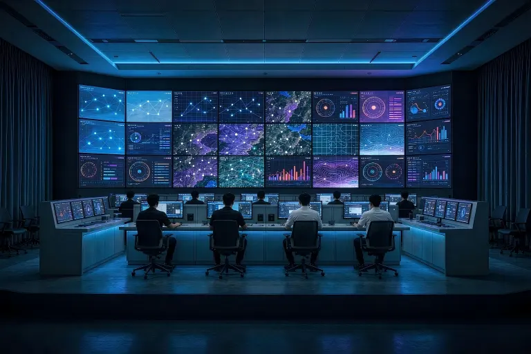
COB's core markets—command & control rooms, broadcast and virtual production, premium corporate displays—all involve long viewing hours at close range. Viewers sit meters away; mosaicism has nowhere to hide.
The good news: modern point-by-point calibration systems treat COB well. Factory calibration plus periodic on-site recalibration (camera-based capture, coefficient write-back to receiving cards, data stored with the display) keeps a COB wall at factory-grade uniformity for years of service. For engineers, mastering calibration means holding the lifecycle-quality key to every COB display project.
05Key Takeaways
| Module | One-line takeaway | Memory anchor |
|---|---|---|
| Calibration | Measure → coefficients → write-back | Standard process, not luxury |
| Variation sources | Binning, batch, driver, temperature, aging | "Two by birth, three by service" |
| Luminance | cd/m²; the eye is forgiving | Defines "how bright" |
| Chromaticity | CIE (x, y); the eye is demanding | The main battlefield |
| Gamma | Power-function transfer, typically 2.2 | Low gray = trouble zone |
| COB | No single-lamp repair | Calibration is the lifeline |
Quick self-check: narrate the storyline without looking back—why variation exists → which quantities it shows up in → how calibration removes it. If that chain flows, the later chapters on point-by-point workflows and coefficient generation will fall into place.
06FAQ
Q1: How often should an LED display be calibrated?
Factory calibration is mandatory. On-site recalibration frequency depends on usage and environment—heavy-duty walls should be assessed annually; recalibrate as soon as visible mosaicism or color patches appear.
Q2: Can brightness and chromaticity calibration be done separately?
Technically yes, but they're usually performed together. Chromaticity calibration re-balances the RGB mixture and typically costs brightness—set luminance and chromaticity targets jointly.
Q3: Can COB LED displays be calibrated on site?
Yes. Camera-based point-by-point capture with coefficient write-back to receiving cards works for COB—and it's the primary method for maintaining long-term uniformity on COB walls.
Q4: Should gamma be 2.2 or 2.8?
2.2 aligns with sRGB and mainstream video standards—the safest default. 2.8 gives a steeper curve with punchier contrast, common in broadcast or specific display preferences. Follow your content source and project targets.
Specifying COB display solutions for control rooms, virtual production or corporate environments? Get spec sheets and technical parameters for products backed by factory point-by-point calibration and on-site recalibration support—our engineering team helps you evaluate calibration capability before you commit.
Get COB Display Specs & Calibration DetailsThis article is an original editorial adaptation based on the knowledge framework of Chapter 1, "Calibration Basics," of the textbook LED Display Calibration Technology (Nova StarCloud). It is intended for technical education and does not represent the official textbook text. All rights to Nova StarCloud and the textbook belong to their respective owners.