COB LED DISPLAY · TECHNICAL SELECTION GUIDE
COB LED Module Selection Guide: How Flip-Chip Fine-Pitch COB Ends SMD Lamp Drop Failure
Updated August 2026 · 8 min read · Keywords: COB LED Module / Flip-Chip COB Module / Fine-Pitch COB Module
The Industry Pain Point: SMD Fine-Pitch's "Lamp Drop" Problem
Anyone who has run an SMD fine-pitch project knows these failure modes by heart:
- Lamp drop: SMD lamps are held by two metal bracket legs soldered to the PCB. At fine pitch, joints get smaller and denser — transport vibration and thermal cycling eventually cause cold joints, leaving clusters of dead pixels on the screen;
- Fragile surface: lamp bodies protrude above the PCB. Wiping the screen, handling modules, or even finger pressure can damage them;
- One bump, total loss: a corner impact can shear off entire rows of lamps — unrepairable on site, the whole module gets scrapped.
For command centers and surveillance rooms running 24/7, these structural flaws translate into continuous maintenance cost and downtime risk. COB LED modules are the technology that fixes the problem at the packaging level.
How COB Modules Work: Why They Structurally Cannot Drop Lamps
COB (Chip on Board) module manufacturing comes down to two steps — and each one structurally outclasses SMD:
Step 1: Bare-die direct bonding
R, G, and B LED bare chips are bonded directly onto the PCB — no brackets, no packaged lamps, no reflow soldering. The "bracket + solder leg" structure that makes SMD lamps fall off is never created in the first place.
Step 2: Integral resin encapsulation
The entire display face is encapsulated in one pour of epoxy resin, forming a dense, smooth protective layer. Nothing protrudes — the surface is flat like glass. Scratch resistance, impact resistance, dust and moisture protection: all solved in a single step.
Face-Up COB vs Flip-Chip COB: One Word, Real Performance Difference
Fine-pitch COB modules on the market split into two camps by chip electrode orientation — always confirm which one you're being quoted:
Face-Up COB Module
- Electrodes face up; wire bonding (gold wires) required
- Mature process, lower cost
- Small residual risk of wire breakage
- Thermal path: chip → bonding adhesive → PCB
Flip-Chip COB Module Mainstream
- Electrodes face down; chips interconnect directly with PCB pads
- No gold wires: wire-break failure mode eliminated entirely
- Better thermal path: heat flows through solder directly into the PCB
- Higher reliability — built for 7×24 demanding environments
One-line distinction: face-up hangs on wires, flip-chip stands on pads. When the budget allows and reliability matters, flip-chip COB modules are the safer bet.
Core Value of Real-Pixel COB Modules
1. 1:1 Physical Pixels — Zero Algorithmic Loss on Text and Images
Fine-pitch COB modules use a real-pixel architecture: every displayed pixel is built from its own R, G, B chips, one-to-one with the physical layout. Small fonts render with crisp edges; dense data tables stay perfectly legible — exactly the imaging quality that monitoring centers and dispatch walls demand, with none of the text softness associated with virtual-pixel approaches.
2. Integral Encapsulation: Scratch-Proof, Impact-Resistant, Dust & Moisture Sealed
The dense resin surface lets you clean COB modules with a lint-free cloth without a second thought, and knocks during handling no longer shear off lamps. The encapsulation layer also blocks dust and moisture at the chip level — long-term stability in harsh environments far beyond SMD.
3. High Contrast with Superb Black Uniformity
The COB display face is one continuous deep-black resin surface — no SMD epoxy-body reflections, no lamp-to-lamp variation. Black fields are uniformly deep across the whole screen, with contrast typically at the 10,000:1 class. Dark-scene detail stays rich, and eye fatigue stays low over long viewing sessions.
4. Superior Thermal Design, Slower Lumen Decay
Chips are bonded directly to the PCB, so heat takes the shortest possible path into the board and cabinet structure — no SMD bracket bottleneck. Lower junction temperature → slower lumen decay → longer life. This is precisely why COB modules can credibly promise 7×24 operation.
5. Magnetic Mounting & Hot-Swap Maintenance — Built for Large Tiled Walls
Fine-pitch COB modules widely support magnetic front-service mounting — modules snap onto the cabinet with strong magnets and detach from the front. Hot-swap support means a failed module is replaced in minutes, screen running, no disassembly. For wall-flush installations with rear-access restrictions, this single feature decides whether the project is even feasible.
Where They Belong: 7×24 Mission-Critical Projects
🚨 Command Centers
Round-the-clock reliability
📹 Surveillance Rooms
Crisp small-font telemetry
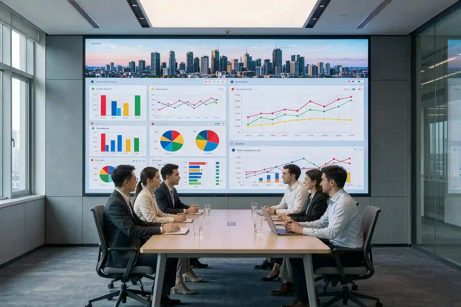
🏢 Executive Boardrooms
Video + text, both strong
📺 Broadcast Studios
High contrast on camera
🏥 Energy / Transport / Healthcare
Displays that can't go down
COB Module vs SMD Fine-Pitch Module: The Full Picture
| Dimension | COB Module | SMD Fine-Pitch Module |
|---|---|---|
| Packaging Structure | Bare-die bonding + integral resin encapsulation | Bracketed lamps + reflow soldering |
| Lamp Drop Risk | Eliminated structurally | High cold-joint risk |
| Surface Protection | Flat & dense: scratch/impact/dust/moisture resistant | Protruding lamps, fragile |
| Thermal Path | Chip → PCB direct, low thermal resistance | Chip → bracket → joint → PCB, high resistance |
| Contrast / Black Level | 10,000:1 class, uniform ink black | Epoxy reflections, grayish black |
| Maintenance | Magnetic front-service, hot-swap, minutes per module | Module RMA or on-site lamp rework |
| 7×24 Fitness | Excellent | Moderate; needs heavy upkeep |
| Cost | Higher upfront, lowest life-cycle cost | Lower upfront, replacement costs accumulate |
Procurement Guide: Six Must-Check Specifications
Put these six items in your RFQ comparison sheet — they'll filter out most low-quality proposals:
① Pixel Pitch
Match pitch to viewing distance: 3m+ → P1.5–P1.8; 2–3m → P1.2–P1.5; under 2m → P0.9–P1.2. Smaller isn't automatically better — matching the distance is what pays.
② Face-Up or Flip-Chip
Confirm exactly which technology you're quoted. Flip-chip means no wires and better thermals — first choice for 7×24 projects. Face-up is a valid budget option for display-oriented applications.
③ Ingress Protection
Ask for documented IP ratings and salt-spray / damp-heat test reports — non-negotiable for humid or dusty installation environments.
④ Module Dimensions
Verify how module size maps onto your final screen dimensions — edge trimming requirements and seam consistency — so tiles align cleanly on site.
⑤ Connector Solution
Power and signal connector brand and foolproofing design directly affect long-term reliability. Confirm hot-swap and blind-mate alignment support.
⑥ Certifications
For export projects: CE, FCC, RoHS, ETL per target market. Energy, transport, and government projects may require additional sector-specific certifications.
FAQ: COB LED Modules, Answered
It's fundamentally a packaging structure difference: SMD solders pre-packaged bracketed lamps onto the PCB; COB bonds bare chips directly to the PCB and encapsulates the whole face in resin. That single difference cascades into five advantages — reliability (lamp drop), surface protection, thermal performance, contrast, and maintenance — and COB usually wins total cost of ownership over the full life cycle.
Yes — and it's simpler than SMD. Fine-pitch COB modules support magnetic front-service mounting with hot-swap: detach the failed module from the front, snap in a spare, done in minutes without shutting down. SMD lamp drop means lamp-by-lamp rework or a full module RMA. We recommend budgeting 1%–3% spare modules per project.
Yes — this is COB's home turf. Flip-chip COB conducts heat from the chip through solder directly into the PCB, keeping junction temperature low and lumen decay slow; the no-wire design removes the wire-break failure mode. Command centers, surveillance rooms, and energy dispatch walls have validated continuous operation in the field. Pair with adequate cabinet cooling and redundant power for maximum 7×24 stability.
Send Your Project Specs — Get a COB Module Proposal & Quote
Tell us your screen dimensions, installation environment, viewing distance, and runtime requirements — we'll return a tailored proposal within 1 business day: pitch selection, face-up vs flip-chip recommendation, module layout drawing, and full-screen quotation.
Get Module Proposal & Quote →Drawing review · Spare-parts planning · Target-market certification check