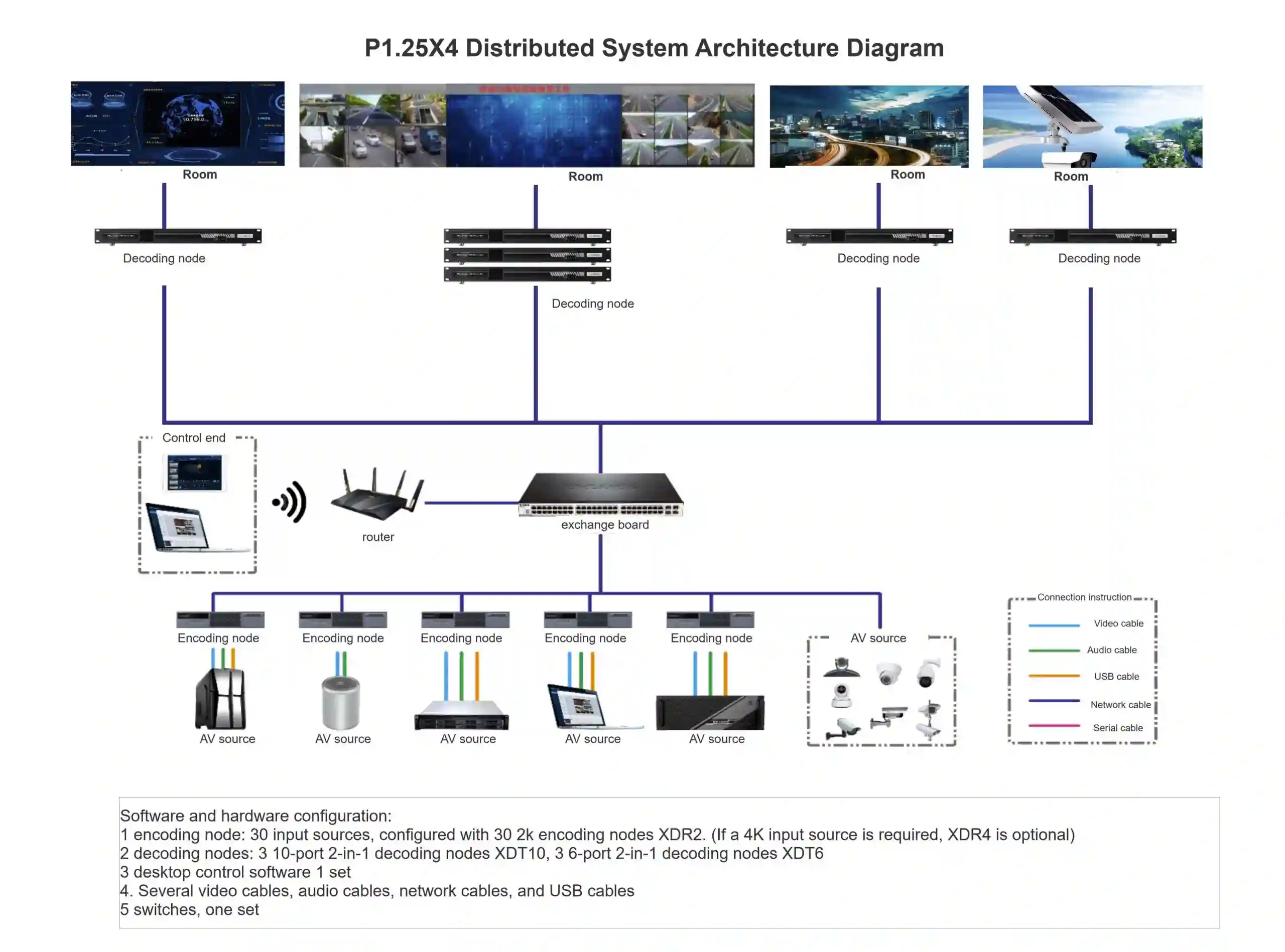
Data Center Video Wall Guide: COB LED Display + LED Video Wall Controller Integration
Data Center Visualization COB LED Wall Video Wall Controller
When the main wall needs to render KPI dashboards, map alerts and live trend curves in parallel — and side screens need to show multiple business subsystem dashboards side by side — the old "projector + LCD video wall + matrix switcher" stack is hitting its limits. A COB LED display paired with a modern LED video wall controller is redefining what's possible in 24×7 data center visualization.
Why does the data center video wall need to be re-selected?
A typical data center visualization wall has to carry at least three categories of source signals: (1) business KPI dashboards, (2) multi-subsystem BI panels, and (3) map / topology / process visuals on the main canvas. Each of these has different requirements — the main screen demands high resolution, low latency, and colour consistency over static display; the side screens demand independent zones, per-zone refresh and the ability to overlay dynamic charts.
For years, many IT and operations teams chose LCD video wall + matrix switcher + image processor. It is stable in the short term, but as business subsystems multiply and resolution needs shift from 1080P to 4K/8K with 24×7 uptime, three cracks appear:
- Bezels and colour drift: physical bezels break the canvas; after long run-time, screens drift apart in colour temperature.
- Signal spaghetti: every additional HDMI/DP/IP source means another matrix port or another cable; B/S control software and C/S decoding software live in separate worlds and frequently conflict on upgrades.
- High maintenance cost: a single bad LCD panel takes the whole unit down; a failed matrix port breaks the whole signal path; mean-time-to-repair balloons.
By contrast, the modern COB LED display + LED video wall controller stack folds display, processing and control into one remotely-operable system — true 24×7 rendering, multi-source overlay on a single canvas, and millisecond alert linkage.
How a COB LED Display solves three hard display-layer problems
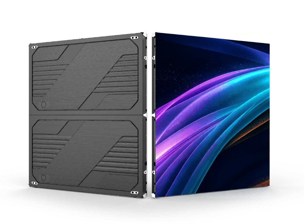
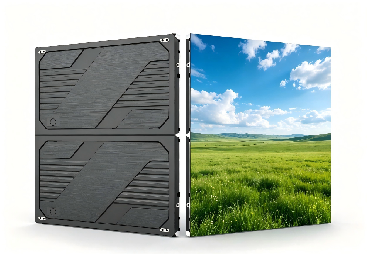
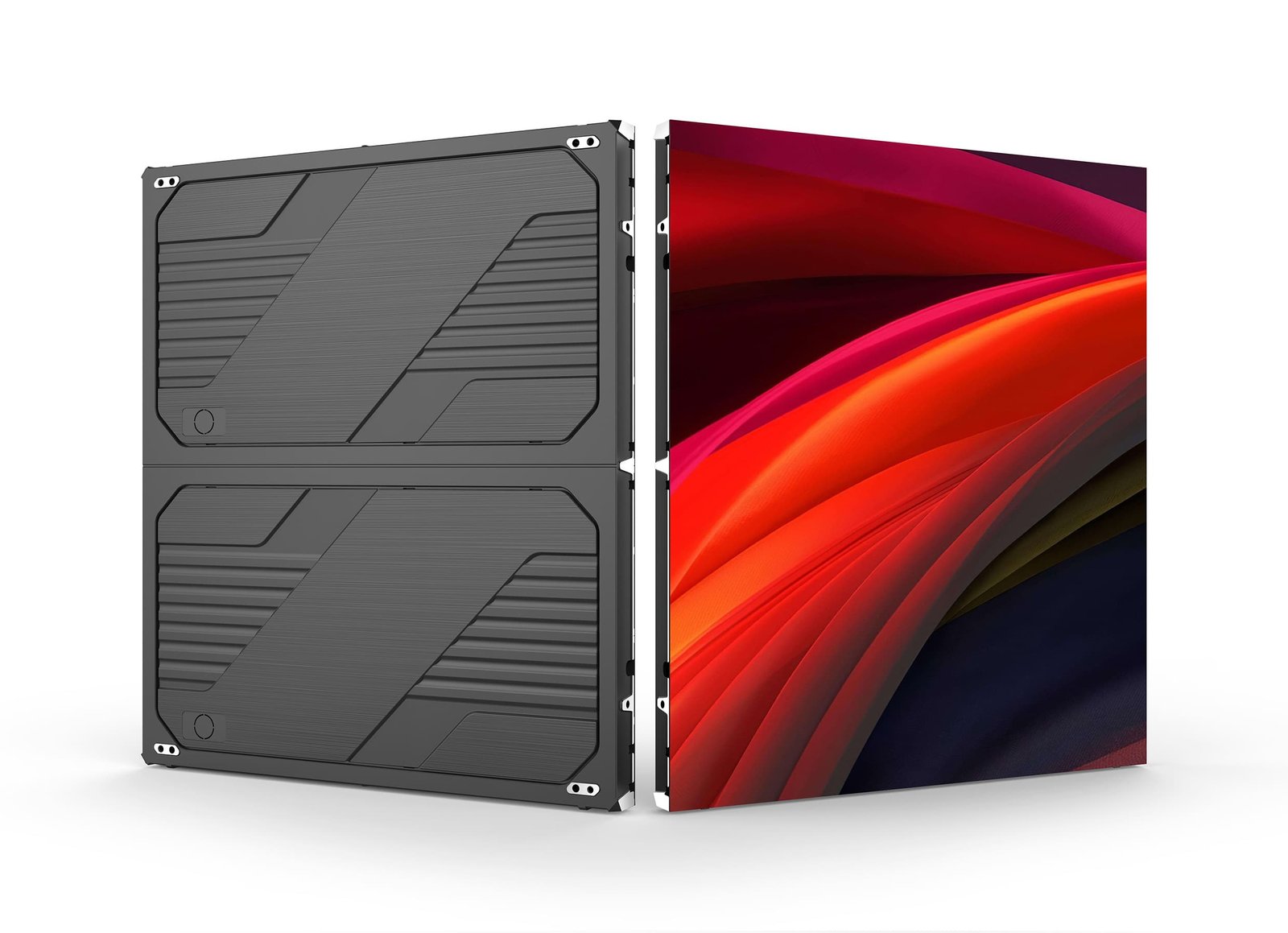
COB (Chip-on-Board) mounts LED chips directly on the PCB, in contrast to traditional SMD surface-mount. The three key differences — sealed solder joints, smaller achievable pixel pitch (P0.6/P0.9/P1.2), and better cabinet flatness — line up almost exactly with the three pain points in data center visualization:
| Engineering pain point | SMD LED wall | COB LED display |
|---|---|---|
| Up-close viewing | Lamp beads visible, granulation at sub-P1.5 | P0.9 / P1.2 still renders clean at a 2.5 m viewing distance |
| Impact / dust / cleaning | Lamp beads exposed; no pressure on the surface | Encapsulation layer covers the chips; wipe-clean surface |
| Colour temperature consistency | CCT drift across cabinets after long uptime | Stronger cabinet-to-cabinet optical consistency |
| Thermal / lifetime | Longer thermal path, faster lumen decay | Shorter thermal path, longer typical lifetime |
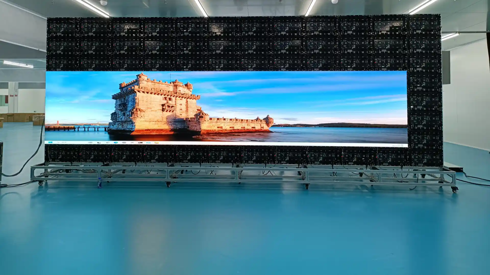
The most visible day-one benefit for operators: a COB LED video wall looks like one continuous canvas. The seams between main and side screens are nearly invisible — exactly the visual difference between a true data visualization wall and a legacy LCD video wall.
LED Video Wall Controller: multi-source + splicing + sending in one box
A qualified LED video wall controller must do four jobs at once: signal acquisition, splicing / windowing / roaming, LED wall loading and calibration, and remote O&M. Placed between the data center and the COB LED display, it collapses what used to be "matrix + image processor + sending card + monitoring server" into one device.
- Multi-source inputs: IP video streams, HDMI 2.0, DP 1.2, 3G-SDI, VGA — main and side walls can independently pull sources.
- True 4K pipeline: 4K×2K@60Hz, RGB 4:4:4 end-to-end without compression, no frame drops and no colour banding.
- Multi-layer overlay: dozens of layers, cross-screen roaming, picture-in-picture; KPI and alerts stack on independent layers.
- 7×24 hot backup: input source redundancy + dual PSU + device-level primary/standby, high SLA achievable.
- Browser-based control: B/S web architecture, no client install, cross-platform operation.
The "1+N+1" architecture mapped to your data center
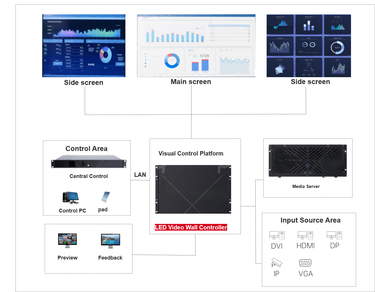
The capabilities above can be summarised as a "1+N+1" architecture: 1 main visualization wall built from a COB LED display, N business subsystem source streams, and 1 LED video wall controller (a.k.a. LED video wall processor / video wall processor) that unifies everything.
| Layer | Component | Typical config | What to validate |
|---|---|---|---|
| Display | COB LED video wall | P0.9 / P1.2 pitch, main wall 6×3.4 m, side wall 2.2×1.5 m | Refresh rate, CCT uniformity, panel flatness |
| Processing | LED video wall controller | 2U / 4U rack, modular cards | Loading capacity, layer count, hot-backup mechanism |
| Input | Source signals | IP cameras, BI systems, map platforms, KPI APIs | Protocol coverage, concurrent sessions |
| Control | Control PC / tablet | Web access, cross-platform | Role-based access, audit trail |
| O&M | Media server / preview monitors | Preview + feedback monitors | Alert latency, MTTR |
The single most important decision in this stack is the video wall controller — it dictates whether the wall runs at 1080P or true 4K, single-layer or dozens of roaming layers, single-box or hot-swappable. Use this short list when comparing vendors:
| Your critical requirement | What the video wall controller must deliver |
|---|---|
| Main screen ≥ 4K with split-screen KPI + map | ≥ 26 million pixel loading, 4:4:4 end-to-end |
| Side screens with 6+ independent subsystem dashboards | At least 16 layers, no layer drop on cross-screen roaming |
| 7×24 with no single point of failure | Input hot-backup + dual PSU + device-level redundancy |
| Cross-platform remote O&M | Browser-based (B/S), no client install |
| Real-time alert linkage, latency-sensitive | Built-in low-latency render path, alert push < 60 ms |
During POC, we recommend at least these three test scripts: 1) long-duration static colour-temperature drift, 2) multi-layer overlay / roaming smoothness, 3) primary-to-standby source switchover latency. These cover ~80 % of runtime scenarios.
Common deployment pitfalls
- Only chasing pixel pitch numbers, ignoring cabinet-level CCT uniformity — at the same nominal P1.2, different brands and batches can drift by 800K; main and side screens will not match.
- Treating the LED video wall controller as a sending card — you lose the multi-layer, low-latency and hot-backup advantages.
- Single point of failure in the chain — a single box, single PSU, single input is no different from the legacy LCD video wall era.
- Ops not ticketised — the browser is only the entry point; real MTTR reduction needs role-based access, change logs and alert routing.
A three-step path from "looking at the wall" to "using the wall"
If you're evaluating or upgrading a data center visualization wall, the following path is directly reusable:
- List the requirements. Capture five dimensions, source signals, display area, pixel pitch, hot-backup needed (Y/N), remote O&M needed (Y/N). in a spreadsheet with quantified criteria (pixel count, signal protocol, max concurrency).
- Benchmark the shortlist. Pick 2–3 LED video wall controller vendors and request their spec sheets and POC test scripts. For the COB LED display, also evaluate "chip packaging process" and "cabinet-level optical uniformity" as soft criteria.
- Phase the acceptance. Split acceptance into four checkpoints: (a) single-device factory acceptance, (b) source signal integration, (c) 72-hour stability soak, (d) end-to-end alert pipeline validation — each with a clear pass/fail bar.
📩 Download the COB LED Display + LED Video Wall Controller Selection Checklist (PDF)
For deeper guidance on model-level differences, COB LED video wall behaviour at P0.9 / P1.2 pitch, and reference deployments in command center / control room / meeting room scenarios, see our full solution library — hardware BoM to phased implementation templates included.
Frequently asked questions
Q1: Is an LED video wall controller the same as an LED video processor?
Strictly speaking, a video wall processor emphasises "splicing", and an LED video wall controller combines "splicing + LED loading + remote control" in one device. Today's mainstream 2U / 4U rack controllers embed the sending-card function, so they can be viewed as "embedded video wall processor + sending card".
Q2: What's the biggest operational difference between COB LED display and SMD LED display?
COB encapsulates the LED chips under a sealed surface, so the panel is wipe-clean, more static- and dust-tolerant. SMD leaves lamp beads exposed and cannot be pressed during cleaning. Long-term, COB also delivers better cabinet-to-cabinet colour uniformity.
Q3: For a ~100 m² visualization wall, should we pick P0.9 or P1.2?
It depends on viewing distance. At 2.5–4 m, P1.2 offers the best cost / quality balance; under 2.5 m with budget headroom, P0.9 is recommended.
Q4: If signals are mostly IP streams, what specs should the controller meet?
At minimum: H.264 / H.265 support and N-channel concurrent de-encapsulation (N sized to your subsystem count). Make sure the same controller also exposes HDMI 2.0 / DP 1.2 as a fallback when the IP stream fails.
#COB LED display #COB LED video wall #LED video wall controller #video wall processor #control room display #data visualization wall #LED display controller
Based on field experience with COB LED displays and LED video wall controllers in data center visualization projects. Always confirm the latest vendor specifications before procurement.