Command Center Video Wall Architecture: How an LED Video Wall Controller Unifies Control, Visual & Input Zones
Command Center Hardware-Software Synergy Video Wall Controller
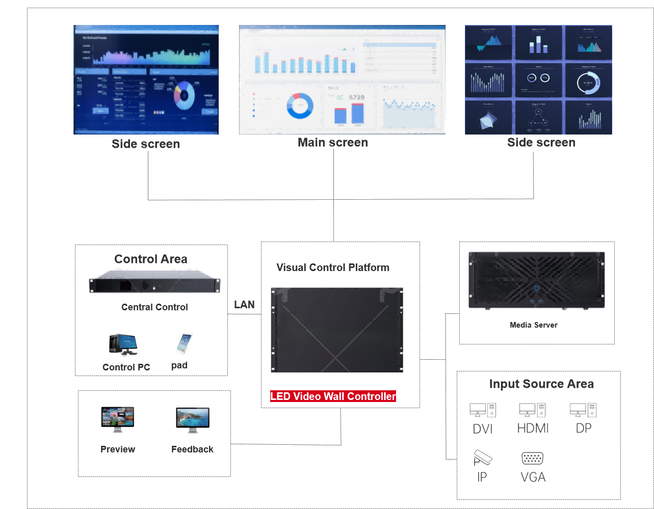
A complete command center visualization system can be split into three functional zones — Control Area, Visual Control Platform, and Input Source Area — bound together by LAN. Sitting in the middle, the LED video wall controller (a.k.a. video wall processor) is both the signal aggregation point and the single accountable brain for the wall. Its capability ceiling decides the entire stack's scalability, stability and serviceability.
The three "fractures" silently eating your command-center O&M budget
Across emergency operations, transit OCC, energy dispatch and airport tower command centers, we keep seeing the same problem: the system technically runs, but operationally it feels broken. The three fractures are:
- Spatial fracture: operator consoles, the display wall and source racks live in physically separate zones — every signal reroute involves a walk through three rooms.
- Protocol fracture: camera feeds on IP, surveillance on SDI, BI on HDMI, legacy business systems on VGA — one protocol, one device, and the more devices, the larger the fault surface.
- Accountability fracture: display faults blame vendor A, matrix faults blame vendor B, splicing faults blame vendor C — three vendors coordinate on every incident, and MTTR balloons.
In a typical "un-architectured" command center, the rack is jammed with matrix switchers, splicers, sending cards, decoders and transcoding gateways. Each of these devices "works on its own", but together they drain 24×7 cooling and power budgets and slow down every dispatch. The fix isn't "buy a bigger matrix" — it's redesigning control, display and input as one integrated system. That is exactly the role a LED video wall controller is built for.
One diagram, three zones, one central device
Project the command center system onto a single diagram and you can see three functional zones with one central device:
Control Area
Visual Control Platform
Input Source Area
LED Wall Output
Operation
The two key design choices are LAN-based unified dispatch and one central device: the LED video wall controller is no longer hiding at the bottom of a rack — it's explicitly placed in the Visual Control Platform position. Northbound it serves every command from the Control Area, southbound it ingests every signal from the Input Source Area, eastbound it links the Media Server, and at the operation side it feeds the Preview and Feedback monitors for end-to-end visual validation.
1) Control Area — how humans "command" the wall
The Control Area is where humans sit: Central Control workstation, mobile dispatch pad, shift-leader console. As long as LAN reach is in place, these terminals access the LED video wall controller via a B/S browser console — replacing the old habit of flipping between C/S clients and Web dashboards for every action.
One specific capability worth configuring is role-based access. Operators can only trigger pre-set scenes. Shift leaders can swap a source on the fly. System admins can re-create the entire wall layout. Field engineers can pull logs or push firmware remotely. Tight role-based access is effectively the compliance foundation for the whole stack — operation trail and change audit included.
2) Visual Control Platform — the wall's accountable brain
This layer is the heart of the architecture — the LED video wall controller itself. It must satisfy four core requirements simultaneously:
| Core capability | Measurable criteria | Common pitfalls |
|---|---|---|
| Multi-source inputs | Concurrent IP, HDMI 2.0, DP 1.2, DVI, VGA | Only physical ports; missing IP stream concurrency |
| True 4K pipeline | 4K×2K@60Hz, RGB 4:4:4, 10-bit colour depth | Compressed transport → banding & drops |
| Multi-layer / roaming | 16+ layers, no cross-screen layer loss | Layers halve across screens, alerts hidden |
| 7×24 hot backup | Input / dual PSU / device-level | Single box, single PSU — cheap up front, high risk in life |
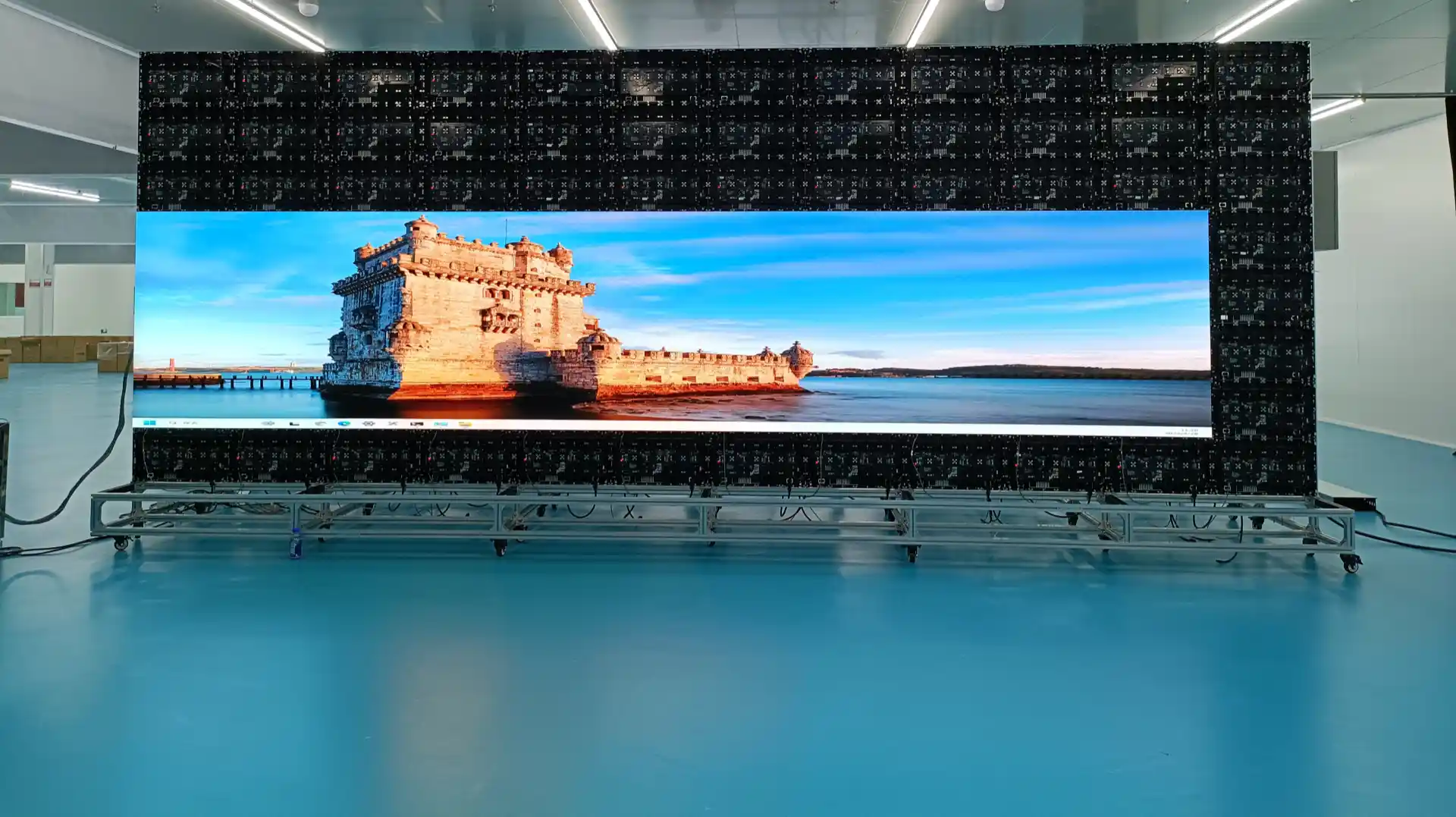
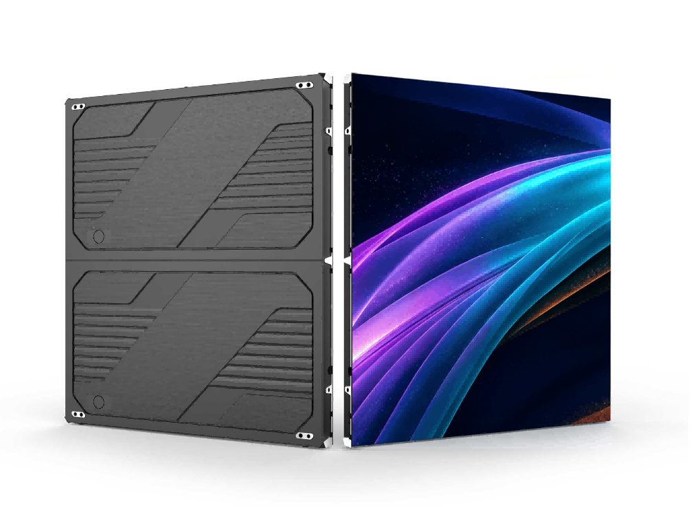
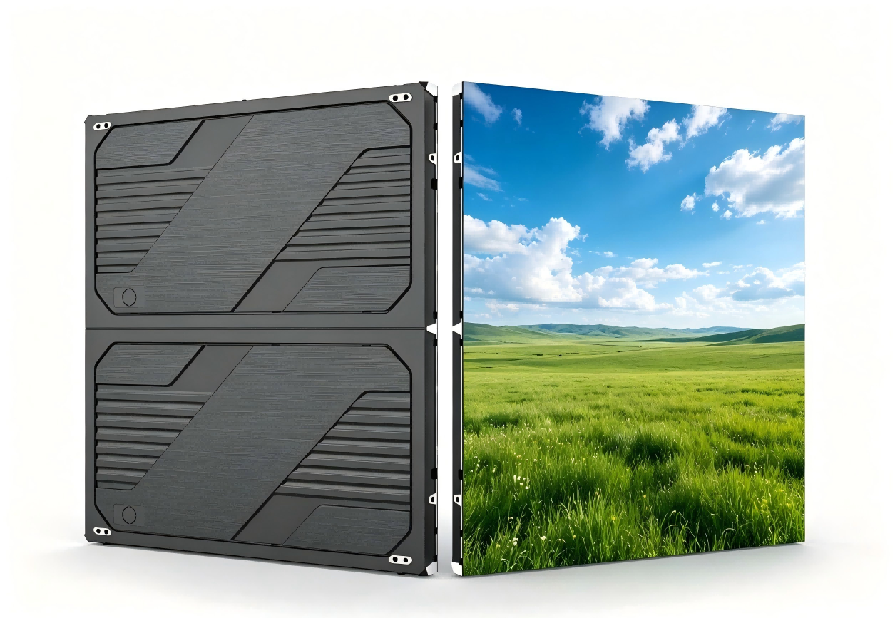
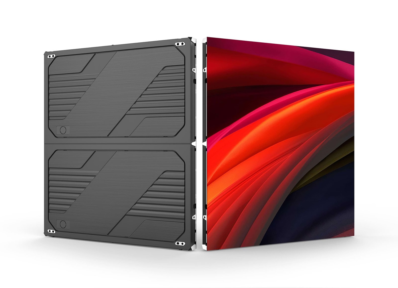
A frequently underestimated spec is loading capacity. The video wall controller's loading directly determines the maximum resolution a connected COB LED display can scale to — it's a prerequisite for any P0.9 / P1.2 fine-pitch wall to come online.
3) Input Source Area — protocol diversity is an asset, not a burden
A common instinct is "force everything onto an IP camera stream and we're done". In real projects, BI systems, KPI APIs, map platforms, video conferencing and broadcast systems make multi-protocol coexistence the norm. The right question isn't how to unify upstream — it's whether the controller's protocol coverage is wide enough. Looking at the diagram, DVI / HDMI / DP / IP / VGA coexisting on the input side is exactly the operational norm.
The Media Server is the "back-up source" role: when real-time signals aren't needed, dispatch plans, training clips and emergency PSAs are sent from here to the LED video wall. When a real-time source fails, the Media Server can stand in to prevent a black wall.
Concrete gains across five typical command-center scenarios
| Command-center type | Critical demand | Concrete gain from this architecture |
|---|---|---|
| Emergency operations centre | Burst alerts must surface within seconds | IP stream preview < 60 ms, alert layer pinned on top, never occluded |
| Smart city / city operations | Multiple subsystem visuals coexist | Multi-source multi-layer, no layer drop on cross-screen roaming |
| Transit OCC (rail) | Track map, CCTV and SCADA on one wall | SCADA via IP / HDMI dual-link, automatic primary-standby switchover |
| Airport tower / energy dispatch | Multi-seat collaboration, remote dispatch | Pad / PC browser-based, no client install, role-based access per seat |
| Executive briefing room | Many presets, frequent switches | 2,000 presets, one-tap recall, sub-second switching, no black wall |
8 procurement questions to ask any vendor (a decision-maker's POC checklist)
- What's the maximum pixel loading of the LED video wall controller? (drives future expansion)
- How many simultaneous layers? Does cross-screen output halve the layer count?
- Maximum concurrent IP camera stream sessions? H.265 support?
- Primary-to-standby signal switchover latency, measured under load, in milliseconds?
- After a power-loss / reboot, how long to restore the wall to the previous preset?
- LAN-based unified dispatch supported? Web console truly install-free?
- Role-based access finest grain — per action or only per role?
- Are the dual PSUs hot-swappable? Is device-level hot-backup two identical controllers in mutual standby, or do you need an external switch?
From "architecture" to "POC" to "deploy" in three days
If you're evaluating or refreshing a command-center visualization stack, here is a reliable cadence:
- Day 1 — architecture compare. Put today's topology side-by-side with your target architecture; mark "keep, merge, replace" per device. Half a day of work, but it captures most of the value.
- Day 2 — shortlist vendors. Compare 2–3 video wall controller vendors; in parallel evaluate COB LED display vs. SMD at your target pixel pitch.
- Day 3 onwards — POC. At least four hard tests — multi-source ingest, layer roaming, alert linkage, hot-standby switch — each with a quantifiable pass / fail bar.
📩 Book a free 30-min Command Center Architecture Review
From "where do signals converge" to "who owns the fault", the clarity of the architecture dictates the next five years of O&M cost. The LED video wall controller isn't a silver bullet that replaces every matrix or sending card — but it pulls control, display and input back onto one diagram, where every signal is locatable, traceable, and replaceable.
Frequently asked questions
Q1: Does a command center have to use IP streams? How do we integrate legacy VGA sources?
Not necessarily. A qualified LED video wall controller should accept IP (H.264 / H.265), HDMI 2.0, DP 1.2, DVI, VGA and 3G-SDI concurrently. Legacy VGA sources can be ingested directly with built-in ADC. We still recommend planning a three-year migration toward IP streams alongside the legacy paths.
Q2: Does "LAN-based unified dispatch" mean everything runs on the public Internet?
No. "LAN" here means the isolated local network inside the command center. VLAN segmentation is used to keep Control Area and Input Source Area apart from any external network. Public / WAN isolation is a baseline requirement, separate from the LAN-based dispatch model.
Q3: What's the biggest day-one benefit of a COB LED display in a command center?
Clean up-close visuals (2–4 m viewing) without panel seams, a shorter thermal path for 24-hour operation, and strong cabinet-to-cabinet colour uniformity so the main wall and side walls don't drift on tone.
Q4: How is device-level hot-backup actually implemented?
Two identical LED video wall controllers are paired over LAN. Heartbeat keeps output in lockstep. On a self-detected fault or upstream signal loss, the standby takes over within milliseconds; the wall never goes black.
#LED video wall controller #video wall processor #command center video wall #control room video wall #multi input video wall controller #LAN-based video wall #LED control room display
Based on field experience with command-center visualization topologies across emergency ops, transit, energy and tower operations. Vendor naming (video wall controller / video wall processor / image processor) varies — always confirm the latest vendor spec sheet before procurement.